60 second timer
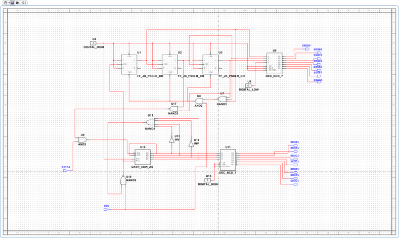
Introduction: In this design problem we had the opportunity to draw together all of the concepts and skills that we have developed pertaining to the topic of synchronous counter design. We will design, simulate and build a Sixty Second Timer. The sixty second timer counts from 00 to 60. This design has two control inputs and two output displays. The two inputs are Clock and Reset. The Clock signal is a 1 Hz square wave that controls the count rate. The Reset signal, when it is a logic zero, resets and holds the count at zero. When the Reset signal is a logic one, counting is enabled. When the count reaches sixty seconds, the counting resets to zero.
Conclusion: In the 60 Second timer first we had to make a truth table that would allow us to check if our
simulation was done correctly. To do a mock trial of this we used P for
President, V for Vice President, S for Secretary and T for Treasurer. The
voting machine essentially checks to see what the majority voted for. Meaning, if three of the four board members
voted for the same thing then the output was a pass. If only 1 or 2 of the 4
people voted for the same thing then the output was a fail. Using this truth
table we wrote an un-simplified logic expression. We had to make it so that it
would satisfy the truth table. We have program we use called Multisim to
simulate the design . It allows us to simulate what a breadboard would do. A
breadboard is what we actually make the circuit on. In Multisim we first used
VCC power for the power source. Then we connected that to the last switch. Each
switch represents the P,V,S,T. Then we connected the first switch to ground.
Ground is the triangle looking thing at the bottom. Next we put in the inverter
bits. They are the ones that give the binary value of 0. I know you have some
knowledge on binary numbers, since it was you who after all convinced me to
become an electrical engineer. After putting in the inverter gates, we added
the AND gates, which were 74LS08’s and then we included the OR gates, which
were 74LS32’s. That is just the type of gates. At the end we attached a probe.
A probe is like an LED at the end that lights up when you have a pass output in
this design. After we ran this simulation, we had to simplify the circuit so
that it would fit on our breadboards when we actually made it. We took our
first logic expression we came up with using the truth table and simplified it
using different theorems we were given. After we came up with our simplified
version of the expression, we simulated that into Multisim. It worked
perfectly! Then we had to breadboard our simulation, by looking at which switch
connected to which gate and use wires given to us to connect it to power and
the chips we put in representing the different types of gates. At the end we
were able to check the truth table using the breadboard.
